 DESIGN OF a 5th ORDER BUTTERWORTH LPF.docx
- 文档编号:4901824
- 上传时间:2023-05-07
- 格式:DOCX
- 页数:11
- 大小:498.06KB
DESIGN OF a 5th ORDER BUTTERWORTH LPF.docx
《DESIGN OF a 5th ORDER BUTTERWORTH LPF.docx》由会员分享,可在线阅读,更多相关《DESIGN OF a 5th ORDER BUTTERWORTH LPF.docx(11页珍藏版)》请在冰点文库上搜索。
DESIGNOFa5thORDERBUTTERWORTHLPF
DESIGNOFa5thORDERBUTTERWORTHLOW-PASSFILTERUSINGSALLEN&KEYCIRCUIT
BackgroundTheory:
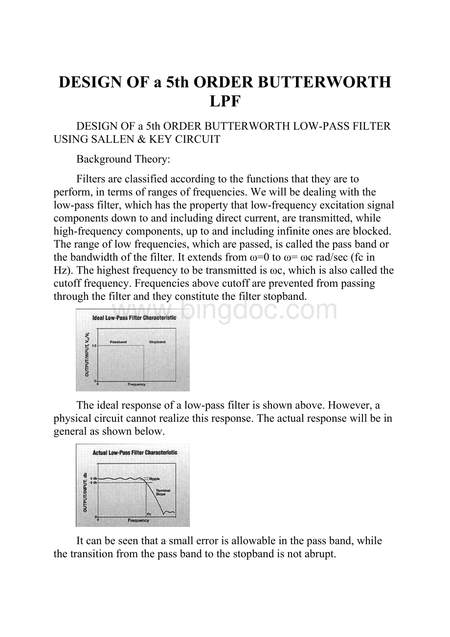
Filtersareclassifiedaccordingtothefunctionsthattheyaretoperform,intermsofrangesoffrequencies.Wewillbedealingwiththelow-passfilter,whichhasthepropertythatlow-frequencyexcitationsignalcomponentsdowntoandincludingdirectcurrent,aretransmitted,whilehigh-frequencycomponents,uptoandincludinginfiniteonesareblocked.Therangeoflowfrequencies,whicharepassed,iscalledthepassbandorthebandwidthofthefilter.Itextendsfromω=0toω=ωcrad/sec(fcinHz).Thehighestfrequencytobetransmittedisωc,whichisalsocalledthecutofffrequency.Frequenciesabovecutoffarepreventedfrompassingthroughthefilterandtheyconstitutethefilterstopband.
Theidealresponseofalow-passfilterisshownabove.However,aphysicalcircuitcannotrealizethisresponse.Theactualresponsewillbeingeneralasshownbelow.
Itcanbeseenthatasmallerrorisallowableinthepassband,whilethetransitionfromthepassbandtothestopbandisnotabrupt.
Thesharpnessofthetransitionfromstopbandtopassbandcanbecontrolledtosomedegreeduringthedesignofalow-passfilter.
Theideallow-passfilterresponsecanbeapproximatedbyarationalfunctionapproximationschemesuchastheButterworthresponse.
TheButterworthResponse
NormalizingH0=1and
Then
findingtherootsofD(s)
Example:
Forn=5
Allthepolesare:
-1.0000
-0.8090+0.5878i
-0.8090-0.5878i
-0.3090+0.9511i
-0.3090-0.9511i
0.3090+0.9511i
0.3090-0.9511i
1.0000
0.8090+0.5878i
0.8090-0.5878
POLELOCATIONS
Thepolesaredistributedoverthecircleofradius1(
).Neverapoleintheimaginaryaxis.
FindingH(s)fromH(s)H(-s):
H(s)isassignedallRHSpolesH(-s)isassignedallLHSpoles
Followingthisprocedure,theButterworthLPFH(s)(H0=1,wc=1rad/sec)canbefoundforvariousfiltersofordern.
WecanuseMATLABtogetthisdenominatorpolynomial(Butterworthpolynomial)
InMATLAB(code):
all_poles=roots([(-1)^n,zeros(1,2*n-1),1])
poles=all_poles(find(real(all_poles)<0))
Den=poly(poles)
CircuitDesign:
WewanttodesignofafifthorderButterworthlow-passfilterwithacutofffrequencyof10KHz.
Duringthedesignwemakeuseofmagnitudeandfrequencyscalingandalsooftheuniformchoiceof
asacharacterizingfrequencywillappearinalldesignsteps,exceptforthelastwherethede-normalized(actual)valueswillbefound.
CircuitImplementation:
ImplementationofthecircuitisdoneusingtheSallen&KeyTopology.
thisisofthegeneralform
Ifk=1,
taking
Torealizea5thorderBLPFoneSallen&Keystagewithasingleop-ampisrequiredforeverycomplex-conjugatepolepair.Sincen=5(odd),anadditionalnegativepoleisrequiredandweuseanRC/voltagefollower.AlsowemadethechoiceofK=1,whichrequiresthattheinvertingop-ampcircuitbereplacedbyavoltagefollowerasshownbelow.
Tofindactualvalues:
Makeallresistors=
Frequencyscaling=
Multiplyingeachcapacitorby
PerformanceMeasures:
Cutofffrequency=10KHz
Frequency(KHz)
Vin(mV)
Vout(mV)
1.502
500
498.5
2.009
500
493.5
5.782
500
493.7
9.001
500
487
9.6
500
387.5
10.04
500
245.7
11.01
500
225.7
12.04
500
187.5
13.02
500
115.6
14.02
500
90.62
15.06
500
75.00
16.01
500
62.50
17.01
500
47.50
Idealresponse:
Actualresponse:
Fromtherecordedvaluesaftermeasurements.
MeasureddBgainvaluesvs.logfrequencyvalues
CircuitDiagram:
FinalCircuit
Parts:
Part
Quantity
LM324N
LowPowerQuadOperationalAmplifier
1
1KΩresistor
5
0.016μFcapacitor
1
0.019μFcapacitor
1
0.013μFcapacitor
1
0.051μFcapacitor
1
0.0049μFcapacitor
1
9Vbattery
2
References:
DeliyannisT.,YichuangSun,andJ.K.Fidler1999,Continuous-timeActiveFilterDesign,CRCPress,NewYork.
VanValkenburgM.E.,AnalogFilterDesign,1982,OxfordUniversityPress,NewYork.
ChenWai-Kai,Passive&ActiveFilterDesign,Chapter2,pp.50-92
HuelsmanL.P.andP.E.Allen,IntroductiontotheTheoryandDesignofActiveFilters


- 配套讲稿:
如PPT文件的首页显示word图标,表示该PPT已包含配套word讲稿。双击word图标可打开word文档。
- 特殊限制:
部分文档作品中含有的国旗、国徽等图片,仅作为作品整体效果示例展示,禁止商用。设计者仅对作品中独创性部分享有著作权。
- 关 键 词:
- DESIGN OF 5th ORDER BUTTERWORTH LPF th
 冰点文库所有资源均是用户自行上传分享,仅供网友学习交流,未经上传用户书面授权,请勿作他用。
 《篮球行进间单手低手投篮》教学设计.docx
-
《饲料添加剂管理条例》知识竞赛试题及答案要点.docx
-
4 物理届高三上学期第一次月考物理试题.docx
-
08第二学期研究生英语.docx
-
31氧气的性质与用途个案教学设计.docx
-
0225变电安规二次题库474道.docx
-
1992年大学英语四级.docx
-
Arts 专项练习.docx
-
《两只鸟蛋》说课稿.docx
-
《孙权劝学》选择阅读带答案.docx
-
《在操场上》教学反思.docx
-
4VMware FT容错原理与配置详解.docx
-
8套专升本艺术概论试题.docx
-
17秋学期《食品安全与日常饮食尔雅》在线作业2.docx
-
3500词汇40篇文章.docx
-
AST中央企业班组长岗位管理能力资格认证三期模拟10300009.docx
-
GMC大赛手册中文版.docx
-
JAVELIN智能球机.docx
-
P1口语重点题型素材更新版.docx
-
QMS质量管理体系审核员真题精选.docx
-
U2t2学教设计.docx
-
XX公路施工组织设计建议书.docx
-
XX省XX县治安拘留所工程建设项目可行性研究报告.docx
-
yy政治知识汇总架构.docx
-
安全生产违法行为行政处罚汇编.docx
-
百度网站的商业运营模式和盈利模式分析.docx
-
保险经营管理重点.docx
-
北极星群和山东群倾情奉献高考题解析5重庆卷.docx
-
《内科学》教学大纲.docx
-
《小学生数学报》全册苏教版六年级下.docx
-
5湖北省三类人员电工试题.docx
-
10食品经营过程与控制制度.docx
-
写景好段摘抄大全.docx
-
小升初满分作文精选10篇.docx
-
新概念第一册知识点总结讲解.docx
-
小学课外活动小组总结.docx
-
小学三年级下册劳动教案最新的.docx
-
小学数学四年级上册期末复习资料.docx
-
小学五年级奥数题集锦及答案.docx
-
小学音乐12册教案全册.docx
-
校本课古筝校本课程教材1.docx
-
新版PEP小学英语三年级下全册教案.docx
-
新疆自治区卷15审阅.docx
-
新课标小学语文四年级下册全册作文第一单元教案2.docx
-
新人教版高二物理期末测试题.docx
-
新苏教版小学五年级数学下册同步集体备课教案教学设计 第三单元练习课.docx
-
修理工年终工作总结.docx
-
项目部安全生产文明施工管理制度.docx
-
新中国六十年道德建设得失之反思.docx
-
心灵成长的故事小学生作文.docx
-
新居民年终总结.docx
